
-
WANTED: Happy members who like to discuss audio and other topics related to our interest. Desire to learn and share knowledge of science required. There are many reviews of audio hardware and expert members to help answer your questions. Click here to have your audio equipment measured for free!
You are using an out of date browser. It may not display this or other websites correctly.
You should upgrade or use an alternative browser.
You should upgrade or use an alternative browser.
AM Radio design improvements
- Thread starter nerdemoji
- Start date
solderdude
Grand Contributor
A floating + input on a 741 opamp.... funny.
More likely someone tried to draw the circuit of a radio using the ZN414 but did not have the right model, the extra transistor output stage helps with the output (K1 is a Xtal earphone)
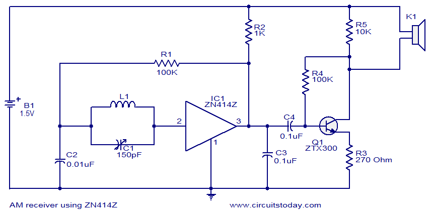
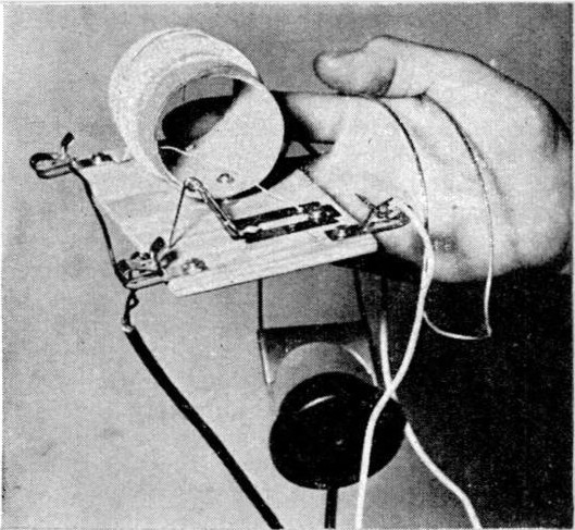
In my youth I made a radio using the ZN414 with the familiar LM386 that could drive a small speaker.
Very, very similar to this:

I should still have it somewhere.
More likely someone tried to draw the circuit of a radio using the ZN414 but did not have the right model, the extra transistor output stage helps with the output (K1 is a Xtal earphone)
In my youth I made a radio using the ZN414 with the familiar LM386 that could drive a small speaker.
Very, very similar to this:
I should still have it somewhere.
Last edited:
Uhhh...This is a working AM radio design, assuming it has been transcribed correctly. Any ideas for improving the sound output level?View attachment 320967
DVDdoug
Major Contributor
- Joined
- May 27, 2021
- Messages
- 3,046
- Likes
- 4,017
That's a radio???
Don't try to drive a speaker with a regular op-amp. It can't put-out the necessary current for a 4 or 8-Ohm speaker.
TI makes lots of "power amplifier" ICs. Most are based on op-amps. The LM386 is popular but is has too much gain for many applications. (With a line level signal you don't need much voltage gain for a low-power amplifier but you need current & power gain.)
solderdude
Grand Contributor
The output of a ZN414 is very low (50mV or so). The LM386 could not make the speaker sound loud enough despite it being in high gain (200x because pin 1 and 8 are connected with a cap).
Last edited:
mhardy6647
Grand Contributor
- Joined
- Dec 12, 2019
- Messages
- 11,438
- Likes
- 24,827
Here's a better one.
No pesky tubes nor transistors.
Good antenna required.

source: http://www.fmamradios.com/XtalTuner.html
The detector can be a modern semiconductor diode, a galena crystal, or delightfully low tech.
 en.wikipedia.org
One may build an FM radio in broadly similar fashion.

source: http://electronbunker.ca/eb/FMCrystalSet.html
No pesky tubes nor transistors.
Good antenna required.
source: http://www.fmamradios.com/XtalTuner.html
The detector can be a modern semiconductor diode, a galena crystal, or delightfully low tech.
Foxhole radio - Wikipedia
One may build an FM radio in broadly similar fashion.
source: http://electronbunker.ca/eb/FMCrystalSet.html
Last edited:
But semiconductor diodes!!! I'd think you'd boot up some proper tube diode detectorsHere's a better one.
No pesky tubes nor transistors.
Good antenna required.
View attachment 320978
source: http://www.fmamradios.com/XtalTuner.html
The detector can be a modern semiconductor diode, a galena crystal, or delightfully low tech.
Foxhole radio - Wikipedia
One may build an FM radio in broadly similar fashion.
View attachment 320979
source: http://electronbunker.ca/eb/FMCrystalSet.html
")
mhardy6647
Grand Contributor
- Joined
- Dec 12, 2019
- Messages
- 11,438
- Likes
- 24,827
That wouldn't be nearly so green!But semiconductor diodes!!! I'd think you'd boot up some proper tube diode detectors
Repurposing an old razor blade and a pencil to a detector -- now that's upcycling.
If hipsters made AM radios...
A small steel wire poking a galena crystal. Go old school.That wouldn't be nearly so green!
Repurposing an old razor blade and a pencil to a detector -- now that's upcycling.
If hipsters made AM radios...
OP
nerdemoji
Active Member
- Joined
- Jul 17, 2023
- Messages
- 194
- Likes
- 304
- Thread Starter
- #10
Jeez, did not expect this many responses so quickly. This is a project for an engineering class I’m in. I have only a basic understanding of how this works, and this op-amp implementation seems quite different from others I have seen. We only have access to these materials at the time, with some other capacitors if we need. Does anyone here know how I might improve this design or create a better one with these materials? Idk
mhardy6647
Grand Contributor
- Joined
- Dec 12, 2019
- Messages
- 11,438
- Likes
- 24,827
Do you -- and this isn't meant to be a snarky question! -- understand how a superheterodyne AM radio circuit works? The long wave (radio frequency, RF) radio signal is picked up by an antenna, amplified (or not), mixed with a local oscillator to produce an intermediate frequency (IF) signal which is amplified, filtered, then detected and used to drive an audio output stage. Look at a simple, classic AM radio design such as an "AA5" five tube vacuum tube radio as your model and guide.Jeez, did not expect this many responses so quickly. This is a project for an engineering class I’m in. I have only a basic understanding of how this works, and this op-amp implementation seems quite different from others I have seen. We only have access to these materials at the time, with some other capacitors if we need. Does anyone here know how I might improve this design or create a better one with these materials? Idk
(note that the 12AV6 tube has three functions built into it -- two diodes and a triode)
source: https://www.worldradiohistory.com/B...ooks/RCA-Receiving-Tube-Manual-1960-RC-20.pdf
Last edited:
Turn that in for your grade and I guarantee your prof will be impressed!Do you -- and this isn't meant to be a snarky question! -- understand how a superheterodyne AM radio circuit works? The long wave (radio frequency, RF) radio signal is picked up by an antenna, amplified (or not), mixed with a local oscillator to produce an intermediate frequency (IF) signal which is amplified, filtered, then detected and used to drive an audio output stage. Look at a simple, classic AM radio design such as an "AA5" five tube vacuum tube radio as your model and guide.
View attachment 320984
(note that the 12AV6 tube has three functions built into it -- two diodes and a triode)
source: https://www.worldradiohistory.com/B...ooks/RCA-Receiving-Tube-Manual-1960-RC-20.pdf
mhardy6647
Grand Contributor
- Joined
- Dec 12, 2019
- Messages
- 11,438
- Likes
- 24,827
I can send him all the parts he needs!
... and a working model for comparison.
Heck, I'd even throw in an isolation transformer, because I'd hate to get sued if anyone were electrocuted by an "AC-DC" (transformerless) power supply!
... and a working model for comparison.
Heck, I'd even throw in an isolation transformer, because I'd hate to get sued if anyone were electrocuted by an "AC-DC" (transformerless) power supply!
mhardy6647
Grand Contributor
- Joined
- Dec 12, 2019
- Messages
- 11,438
- Likes
- 24,827
I guess it wouldn't be good to mention superregenerative radio circuits now, would it?
We may have already discouraged a budding RF engineer. C'est la vie...I guess it wouldn't be good to mention superregenerative radio circuits now, would it?
mhardy6647
Grand Contributor
- Joined
- Dec 12, 2019
- Messages
- 11,438
- Likes
- 24,827
That would be a shame, in all seriousness -- I hope he/she/they are open minded!
EDIT:
And, again, in all seriousness, @Charger -- if you dig around a little in the tech section at World Radio History, you can find "old" (1980s or '90s) hobbyist magazines (and/or book publications) that show designs and background, too, for simple op amp AM radio circuits that actually might be helpful!

e.g., (and FWIW):

source: https://www.worldradiohistory.com/BOOKSHELF-ARH/Technology/Hobbyist-Specials/99-IC-Projects-1984.pdf
or... umm...

source: https://www.worldradiohistory.com/B...nics-Experimenters-Handbook-1994-Winter-a.pdf
I'm not part of the solution, am I?
EDIT:
And, again, in all seriousness, @Charger -- if you dig around a little in the tech section at World Radio History, you can find "old" (1980s or '90s) hobbyist magazines (and/or book publications) that show designs and background, too, for simple op amp AM radio circuits that actually might be helpful!
e.g., (and FWIW):
source: https://www.worldradiohistory.com/BOOKSHELF-ARH/Technology/Hobbyist-Specials/99-IC-Projects-1984.pdf
or... umm...
source: https://www.worldradiohistory.com/B...nics-Experimenters-Handbook-1994-Winter-a.pdf
I'm not part of the solution, am I?
Last edited:
OP
nerdemoji
Active Member
- Joined
- Jul 17, 2023
- Messages
- 194
- Likes
- 304
- Thread Starter
- #17
Well lets go back to the rather silly reason this thread was created. I am a high school student, and our wonderful teacher did not teach us anything. He simply told us to find an online schematic and make it. If it works, you get points, and if it doesn't, you don't. I found this one https://www.wikihow.com/Create-a-Simple-AM-Radio and I made it. It didn't work, so I moved the antenna directly next to the input of the op-amp, and it worked, which made my team the only out of 7 to have a working design. I learned how AM radios worked at a basic level (you need a capacitor and an inductor and that formula and boom you get a resonant frequency). I looked into op-amps and our design seems to be a weird implementation.
Anyway, our circuit isn't very loud and it sound like the signal is clipped (but idk if this is actually the case). I wanted to know if you guys knew how to adjust the wiring to get a better signal.
But then there was the other reason: my friend did not have a working design, and couldn't find any working ones, So I took mine, redrew it with some edits, and posted it here and told them that I found a design on a website called Audio Science Review. Teacher thought that the design here was similar to mine (which it was), and disallowed them from using it. Unfortunate. Pretty much every group fails this project every year because they aren't taught even a modicum of material on the subject. Anyway that old design in the world radio history website that you posted will be helpful for my friend, so thank you very much.
solderdude
Grand Contributor
This circuit cannot possibly work correctly for the simple reason the + input of the opamp is floating (not connected) so the opamp output will go either to + output rail or - output rail voltage.
You either need a detector in there and use the uA741 with tons of gain (and properly used !) or you need to get yourself a ZN414, 415 or 416.
You either need a detector in there and use the uA741 with tons of gain (and properly used !) or you need to get yourself a ZN414, 415 or 416.
Last edited:
All that. And last I checked, a 741 has almost no gain in the AM broadcast band. So even if the circuit "worked" it would be crap. Use solderdude's circuit. Well, unless that 5-tube superhet is calling your nameThis circuit cannot possibly work correctly for the simple reason the + input of the opamp is floating (not connected) so the opamp output will go either to + output rail or - output rail voltage.
You either need a detector in there and use the uA741 with tons of gain (and properly used !) or you need to get yourself a ZN414, 415 or 416.
AnalogSteph
Major Contributor
It's probably some sort of trick circuit that's making use of an IC in unusual ways, as shown here for the LM386:
At least that stands somewhat of a chance of driving an actual speaker. A µA741 "barefoot" is much too wimpy for such a task.
On a side note, ZN414 seems to be long EOL but can be replaced by TA7642.
Generally speaking, there are many ways of skinning this proverbial cat. You always need some form of selectivity to isolate the station to be received (which in the simplest case is provided by the tank circuit's LC resonance), some form of AM demodulation, and amplification to provide enough voltage and current to drive your speaker load. When using a diode detector, you will have the problem of its threshold voltage limiting sensitivity, so having some gain before it will be a good idea, as well as keeping threshold voltage down by using a Schottky diode (the closest thing to a germanium that's still being made these days) and keeping load impedance high. (Some smart people have also resorted to using a minimal amount of DC current to pre-bias the diode so it's closer to the threshold.)
This may be a good opportunity to plug this page of mine that I wrote years ago and which I suspect gets barely any visits:
Last edited:
Similar threads
- Replies
- 5
- Views
- 965
- Replies
- 1
- Views
- 295
- Replies
- 6
- Views
- 351