Amplitude modulation (AM) is a modulation strategy utilized in electronic communication, most normally for transmitting data through a radio carrier wave. In amplitude modulation, the amplitude of the carrier wave changes as per the message signal is transmitting.
There are two stages of AM receiver which are RF and IF. Hence, RF-to-IF receivers incorporate an oscillator with a variable frequency (which differs from RF carrier frequency).
By tuning to the channel, you are tuning the nearby oscillator and RF tunable channel at the equivalent time. All stations provide a fixed carrier frequency for sufficient selectivity.
Hardware Components
The following components are required to make AM Receiver Circuit
| S.no | Components | Value | Qty |
|---|---|---|---|
| 1. | Transistor | BC547 | 1 |
| 2. | Long wire antenna | – | 1 |
| 3. | Coil | 80 turns | 1 |
| 4. | Variable Capacitor | 365pF | 1 |
| 5. | Diode | OA91 | 1 |
| 6. | Resistor | 820K, 22Ω | 1, 1 |
| 7. | Capacitor | 100nF, 10nF, 4.7nF | 2, 1, 1 |
| 8. | Headphones | – | 1 |
| 9. | Battery | 3v | 1 |
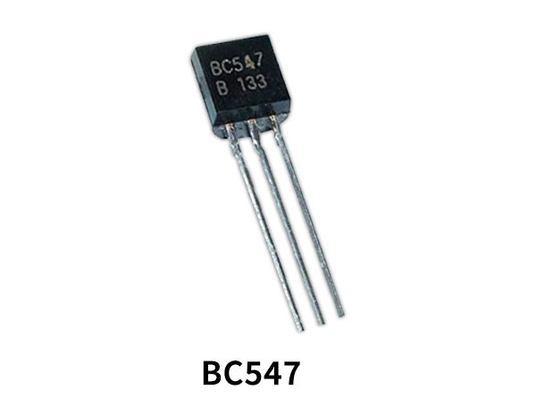
BC547 Pinout

For a detailed description of pinout, dimension features, and specifications download the datasheet of BC547
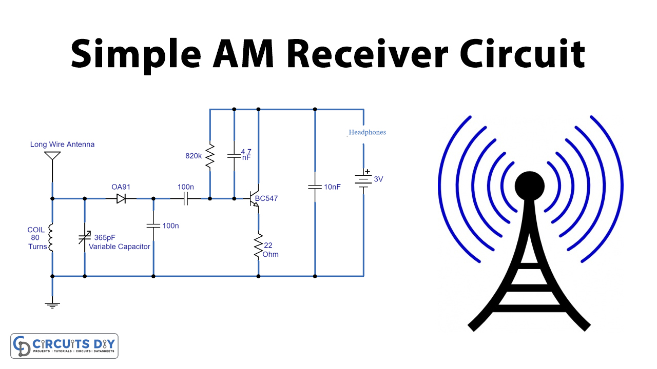
AM Receiver Circuit
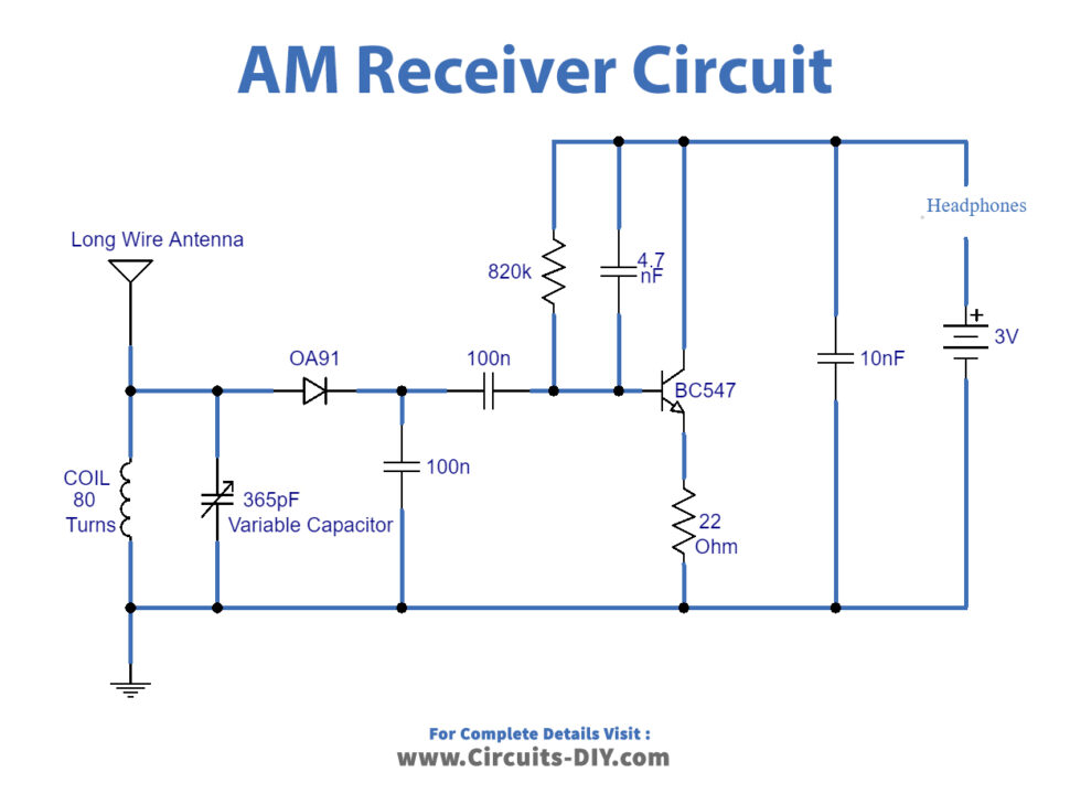
Working Explanation
The schematic that appeared above is a basic AM receiver circuit. It utilizes just a single transistor and a few other small electronic components. In the respective circuit, the coil and 365pF variable capacitor structure the main circuit. Which gets the signals through the antenna which acts as a receiving wire. Afterward, the signal is then identified by the OA91 diode. Further, it is amplified by the BC547 transistor. Curl is equivalent to 80 turns of 26 s.w.g. Enameled copper wire twisted on an unfilled cardboard toilet paper roll or an offcut bit of plastic waste funnel. You can try various coils with the coil found in AM compact radios.
A radio receiver comprises a Radio Frequency (RF) area, an RF-to-IF converter (mixer), An Intermediate Frequency (IF) area, a Demodulator, and an Audio speaker.
For the demodulator to work with any radio signal, we convert the carrier frequency of any radio signal to Intermediate Frequency (IF). The radio receiver utilizes to optimize for that frequency.
Applications and Uses
An AM receiver detects amplitude fluctuations in the radio waves at a specific frequency, at that point, amplification changes the signal voltage to work an amplifier or headphone.