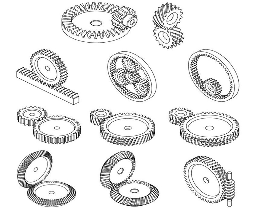
Image Credit: Tewlyx/Shutterstock.com
Gears are toothed, mechanical transmission elements used to transfer motion and power between machine components, and in this article, we discuss the different types of gears available and how gears work. Operating in mated pairs, gears mesh their teeth with the teeth of another corresponding gear or toothed component which prevents slippage during the transmission process. Each gear or toothed component is attached to a machine shaft or base component, therefore when the driving gear (i.e., the gear that provides the initial rotational input) rotates along with its shaft component, the driven gear (i.e., the gear or toothed component which is impacted by the driving gear and exhibits the final output) rotates or translates its shaft component. Depending on the design and construction of the gear pair, the transference of motion between the driving shaft and the driven shaft can result in a change of the direction of rotation or movement. Additionally, if the gears are not of equal sizes, the machine or system experiences a mechanical advantage which allows for a change in the output speed and torque (i.e., the force which causes an object to rotate).
Gears and their mechanical characteristics are widely employed throughout industry to transmit motion and power in a variety of mechanical devices, such as clocks, instrumentation, and equipment, and to reduce or increase speed and torque in a variety of motorized devices, including automobiles, motorcycles, and machines. Other design characteristics, including construction material, gear shape, tooth construction and design, and gear pair configuration, help to classify and categorize the various types of gears available. Each of these gears offers different behaviors and advantages, but the requirements and specifications demanded by a particular motion or power transmission application determine the type of gear most suitable for use.
This article focuses on gears, exploring the various types available and explaining their respective functions and mechanisms. Additionally, this article outlines the selection considerations and common applications for each type of gear.
Gear Design Characteristics
Gears are available in a variety of designs, constructions, and configurations to suit a wide range of industries and applications. These various characteristics allow gears to be classified and categorized in several different ways, which include:
- Gear shape
- Gear tooth design and construction
- Gear axes configuration
Gear Shape
Most types of gears are circular—i.e., the gear teeth are arranged around a cylindrical gear body with a circular face—but some non-circular gears are also available. These gears can feature elliptical, triangular, and square-shaped faces.
Devices and systems which employ circular gears experience constancy in the gear ratios (i.e., the ratio of the output to the input) expressed—both for rotary speed and torque. The constancy of the gear ratio means that given the same input (either speed or torque), the device or system consistently provides the same output speed and torque.
On the other hand, devices and systems which employ non-circular gears experience variable speed and torque ratios. Variable speed and torque enable non-circular gears to fulfill special or irregular motion requirements, such as alternatingly increasing and decreasing output speed, multi-speed, and reversing motion. Additionally, linear gears, such as gear racks, can convert the rotational motion of the driving gear into the translational motion (or a combination of translational and rotational motion) of the driven gear.
Gear Tooth Design
Gear teeth are also referred to as cogs, hence why a gear is also called by the somewhat archaic term of cogwheel. While in the previous section, gears were categorized based on the overall shape of the gear body, this section describes characteristics relating to their tooth (i.e., cog) design and construction. There are several common design and construction options available for gear teeth, including:
- Teeth structure
- Teeth placement
- Tooth profile
Gear Teeth Structure
Depending on the gear structure, gear teeth are either cut directly into the gear blank or inserted as separate, shaped components into the gear blank. For most applications, once a gear succumbs to fatigue, it can be replaced in its entirety. However, the advantage of employing gears with separate tooth components is the ability to individually replace the teeth as each becomes fatigued rather than replacing the whole gear component. This capability may help to reduce the overall cost of gear replacement over time as individual cogs are available at a lower cost compared to that of a complete gear. Additionally, it allows specialized, custom, or otherwise difficult to find gear bodies to be retained and preserved.
Gear Teeth Placement
Gear teeth are cut or inserted on the outer or inner surface of the gear body. In external gears, the teeth are placed on the outer surface of the gear body, pointing outward from the gear center. On the other hand, in internal gears, the teeth are placed on an inner surface of the gear body, pointing inward towards the gear center. In mated pairs, the placement of the gear teeth on each of the gear bodies largely determines the motion of the driven gear.
When both gears in a mated pair are of the external type, the driving gear and driven gear (and their respective shaft or base component) rotate or move in opposite directions. If an application requires the input and output to rotate or move in the same direction, an idler gear (i.e., a gear placed between the driving gear and driven gear) is typically employed to change the direction of rotation of the driven gear.
If one of the mated gear pair is an internal gear and the other is an external gear, both the driving gear and driven gear rotate in the same direction. This type of gear pair configuration removes the need for an idler gear in applications which require the same direction of rotation in the driving and driven gear. Additionally, configurations which employ an internal-external gear pair are suitable for limited- or restricted-space applications as the gears and their shaft or base components can be positioned closer together than is possible with a comparable external-only gear pair.
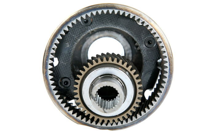
Image Credit: mikeledray/Shutterstock.com
Gear Tooth Profile
The tooth profile of a gear refers to the cross-sectional shape of the gear’s teeth and influences a variety of the gear’s performance characteristics, including the speed ratio and experienced friction. While there are a large number of tooth profiles available for the design and construction of gears, there are three main types of tooth profiles employed—involute, trochoid, and cycloid.
Involute gear teeth follow a shape designated by the involute curve of a circle, which is a locus formed by the end point of an imaginary line tangent to the base circle as the line rolls along the circle’s circumference. Throughout industry, the majority of gears produced employ the involute tooth profile both because of its ease of manufacturing and its smoothness of operation. Compared to some of the other profiles, the involute profile consists of fewer curves, making the manufacturing of involute gear teeth simpler and, consequently, the manufacturing equipment necessary cheaper, which reduces the overall cost of production. The advantage of involute gear teeth lies in their constancy of pressure angle throughout gear engagement and the ability to tolerate variation in the spacing of gear centers without impact to the constancy of the gear ratio for torque and speed. The constancy of pressure angle allows involute gears to run smoother than gears with other tooth profiles and the tolerance of variation allows for greater flexibility within the gear’s design specifications.
Unlike an involute curve where the line rolls along the circumference of a circle, a trochoid curve is a locus formed by a point at a fixed distance (a) from the center of a circle with a given radius (r) as the circle rolls along a straight line. Trochoids are a general category of curves which include cycloids.
- If a<r, then the curve formed is known as a curtate cycloid
- if a=r, then the curve formed is a cycloid
- if a>r, then the curve formed is a prolate cycloid
Compared to the involute gear tooth profile, these profiles are rarely employed for gear design and construction except for use in specialized applications. For example, trochoidal gears are often employed in pumps and cycloidal gears in pressure blowers and clocks. Despite their limited applications, the trochoidal and cycloidal profiles offer a few advantages over the involute profile, including greater tooth durability and elimination of interference.
Gear Axes Configuration
The axes configuration of a gear refers to the orientation of the axes—along which the gear shafts lay and around which the gears rotate—in relation to each other. There are three principal axes configurations employed by gears:
- Parallel
- Intersecting
- Non-parallel, non-intersecting
Parallel Gear Configurations
As indicated by the name, parallel configurations involve gears connected to rotating shafts on parallel axes within the same plane. The rotation of the driving shaft (and the driving gear) is in the opposite direction to that of the driven shaft (and driven gear), and the efficiency of power and motion transmission is typically high. Some of the types of gears which employ parallel configurations include spur gears, helical gears, internal gears, and some variants of rack and pinion gears.
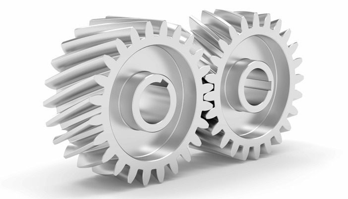
Image Credit: Nuno Andre/Shutterstock.com
Intersecting Gear Configurations
In intersecting configurations, the gear shafts are on intersecting axes within the same plane. Like the parallel configuration, this configuration generally has high transmission efficiencies. Bevel gears—including miter, straight bevel, and spiral bevel gears—are among the group of gears which employ intersecting configurations. Typical applications for intersecting gear pairs include changing the direction of motion within power transmission systems.
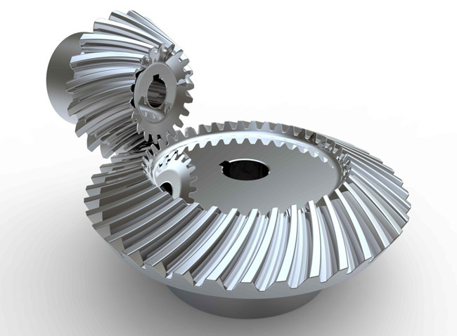
Image Credit: Jim Francis/Shutterstock.com
Non-parallel, Non-intersecting Gear Configurations
Gear pairs with a non-parallel, non-intersecting configuration have shafts existing on axes which cross (i.e., are not parallel) but not on the same plane (i.e., do not intersect). Unlike parallel and intersecting configurations, this configuration generally has low motion and power transmission efficiencies. Some examples of non-parallel, non-intersecting gears include screw gears, worm gears, and hypoid gears.
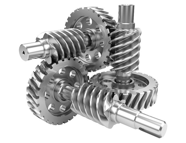
Image Credit: Milos Stojiljkovic/Shutterstock.com
Additional Gear Design Characteristics
Beyond the design characteristics mentioned above, there are several other options an industry professional or procurement agent may consider when designing and selecting a gear for their particular application. Some of the other characteristics which may be considered include construction material, surface treatments, number of teeth, tooth angle, and lubricant type and lubrication method.
Different Types of Gears and Uses
Based on the design characteristics indicated above, there are several different types of gears available. Some of the more common types of gears employed throughout industry include:
- Spur gears
- Helical gears
- Bevel gears
- Worm gears
- Rack and pinion
Spur Gears
The most common type of gears employed, spur gears are constructed with straight teeth cut or inserted parallel to the gear’s shaft on a circular (i.e., cylindrical) gear body. In mated pairs, these gears employ the parallel axes configuration to transmit motion and power. Depending on the application, they can be mated with another spur gear, an internal gear (such as in a planetary gear system), or a gear rack (such as in a rack and pinion gear pair).
The simplicity of the spur gear tooth design allows for both a high degree of precision and easier manufacturability. Other characteristics of spur gears include lack of axial load (i.e., the thrust force parallel to the gear shaft), high-speed and high-load handling, and high efficiency rates. Some of the disadvantages of spur gears are the amount of stress experienced by the gear teeth and noise produced during high-speed applications.
This type of gear is used for a wide range of speed ratios in a variety of mechanical applications, such as clocks, pumps, watering systems, power plant machinery, material handling equipment, and clothes washing and drying machines. If necessary for an application, multiple (i.e., more than two) spur gears can be used in a gear train to provide higher gear reduction.
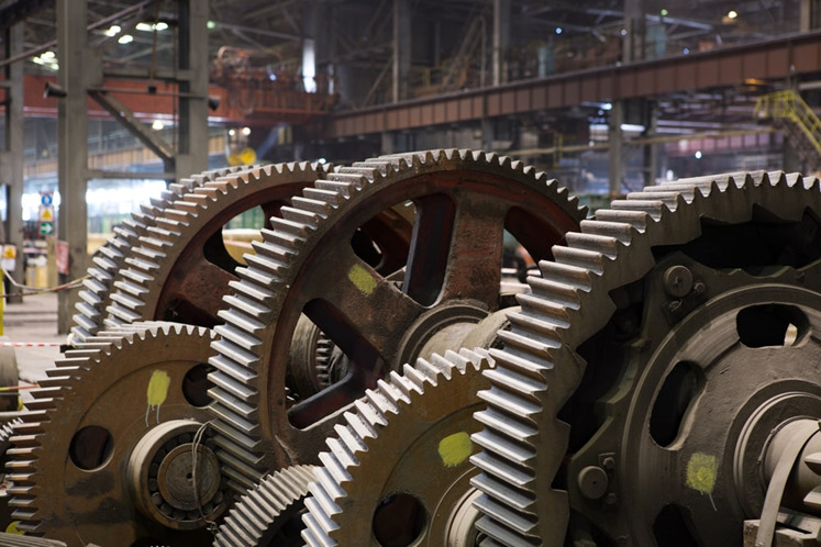
Image Credit: Kuznechik/Shutterstock.com
Helical Gears
Similar to spur gears, helical gears typically employ the parallel axes configuration with mated gear pairs, but, if aligned properly, they can also be used to drive non-parallel, non-intersecting shafts. However, unlike spur gears, these gears are constructed with teeth which twist around the cylindrical gear body at an angle to the gear face. Helical gears are produced with right-hand and left-hand angled teeth with each gear pair comprised of a right-hand and left-hand gear of the same helix angle.
The angled design of helical teeth causes them to engage with other gears differently than the straight teeth of spur gears. As properly matched helical gears come in contact with one another, the level of contact between corresponding teeth increases gradually, rather than engaging the entire tooth at once. This gradual engagement allows for less impact loading on the gear teeth and smoother, quieter operation. Helical gears are also capable of greater load capabilities but operate with less efficiency than spur gears. Further disadvantages include the complexity of the helical tooth design, which increases the degree of difficulty in its manufacturing (and, consequently, the cost) and the fact that the single helical gear tooth design produces axial thrust, which necessitates the employment of thrust bearings in any application which uses single helical gears. This latter necessity further increases the total cost of using helical gears.
As helical gears are also capable of handling high speeds and high loads, they are suitable for the same types of applications as spur gears, such as pumps and generators. Their smoother, quieter operation also suits them for automobile transmissions where spur gears are typically not used.
Single or Double Helical Gear Design
Helical gears are available in single helical and double helical designs. Single helical gears consist of a single row of angled teeth cut or inserted around the perimeter of the gear body, while double helical gears consist of two mirrored rows of angled teeth. The advantage of the latter design is its greater strength and durability (than the single helical design), and the elimination of axial load production.
Additional Helical Gear Designs
Other types of helical gears include herringbone gears and screw gears.
Herringbone: Herringbone gears are a type of double helical teeth in which the two tracks of teeth touch, rather than being separated by a groove, which forms a “V” shape similar to that of the herringbone pattern.
Screw: Screw gears, also called crossed helical gears, are helical gears which are used for non-parallel, non-intersecting configurations. Unlike the helical gears used for parallel configurations, screw gears employ same-hand pairs rather than a right-hand and left-hand gear per pair. These gears have relatively low load capacities and efficiency rates and are not suitable for high power transmission applications.
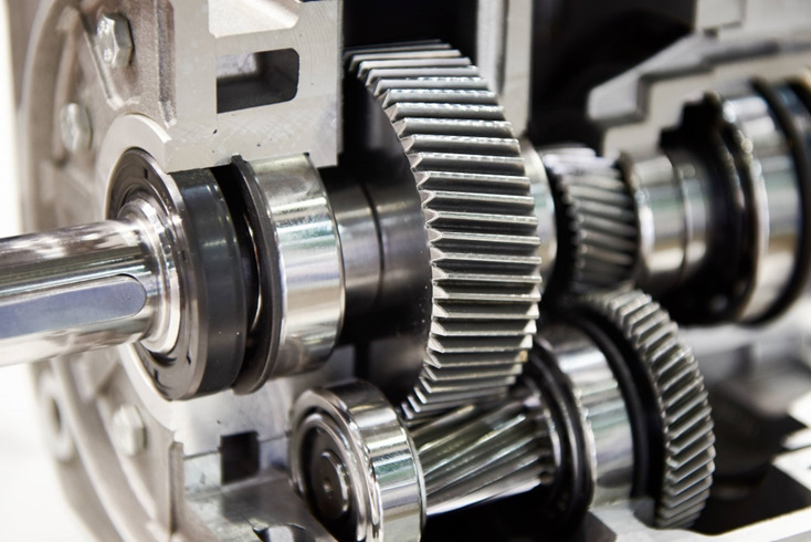
Image Credit: Sergey Ryzhov/Shutterstock.com
Bevel Gears
Bevel gears are cone-shaped gears with teeth placed along the conical surface. These gears are used to transmit motion and power between intersecting shafts in applications which require changes to the axis of rotation. Typically, bevel gears are employed for shaft configurations placed at 90-degree angles, but configurations with lesser or greater angles are also manageable.
There are several types of bevel gears available differentiated mainly by their tooth design. Some of the more common types of bevel gears include straight, spiral, and Zerol® bevel gears.
Straight Bevel Gears
The most commonly used of the bevel gear tooth designs due to its simplicity and, consequently, its ease of manufacturing, straight bevel teeth are designed such that when properly matched straight bevel gears come into contact with one another, their teeth engage together all at once rather than gradually. As is the issue with spur gears, the engagement of straight bevel gear teeth results in high impact, increasing the level of noise produced and amount of stress experienced by the gear teeth, as well as reducing their durability and lifespan.
Spiral Bevel Gears
In spiral bevel gears, the teeth are angled and curved to provide for more gradual tooth engagement and more tooth-to-tooth contact than with a straight bevel gear. This design greatly reduces the vibration and noise produced, especially at high angular velocities (>1,000 rpm). Like helical gears, spiral bevel gears are available with right-hand or left-hand angled teeth. As is also the case with helical gears, these gears are more complex and difficult to manufacture (and, consequently, more expensive), but offer greater tooth strength, smoother operation, and lower levels of noise during operation than straight bevel gears.
Zerol® Bevel Gears
Zerol® bevel gears (a registered trademark of the Gleason Co.) incorporate the design characteristics of both straight and spiral bevel gears with curved teeth placed straight on the conical surface. As the teeth on Zerol® bevel gears are placed as those on straight bevel gears, Zerol® bevel gears can be used in the same as applications as those of straight bevel gears. However, compared to straight bevel gears, Zerol® bevel gears are quieter and experience less friction. Like spiral bevel gears, Zerol® bevel gears are also available in right-hand and left-hand designs, but, unlike spiral bevel gears, Zerol® bevel gears can rotate in both directions since the teeth are not placed at an angle.
Additional Bevel Gear Designs
Other than the types mentioned above, there are several other designs of bevel gears available including miter, crown, and hypoid gears.
Miter: Miter gears are bevel gears which, when paired, have a gear ratio of 1:1. This gear ratio is a result of pairing two miter gears with the same number of teeth. This type of bevel gear is used in applications which require a change only to the axis of rotation with speed remaining constant.
Crown: Crown gears, also referred to as face gears, are cylindrical (rather than conical) bevel gears with teeth cut or inserted perpendicular to the gear face. Crown gears can be paired either with other bevel gears or, depending on the tooth design, spur gears.
Hypoid: Originally developed for the automobile industry, hypoid gears, unlike the previously mentioned types, are a type of spiral bevel gear used for non-parallel, non-intersecting configurations. This design allows for components to be placed lower, allowing for more space in the sections above. Employing curved and angled teeth similar to those used in spiral bevel gears, hypoid gears are even more complex and, consequently, more difficult (and costly) to manufacture.
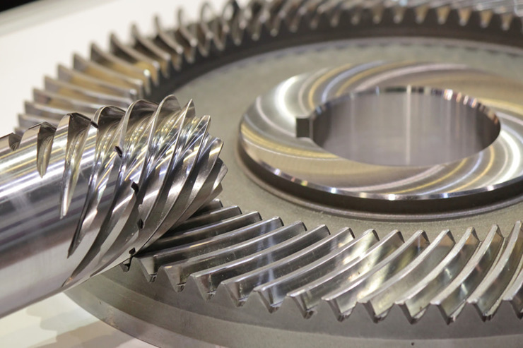
Image Credit: Suriya Desatit/Shutterstock.com
Worm Gears
Worm gear pairs are comprised of a worm wheel—typically a cylindrical gear—paired with a worm—i.e., a screw-shaped gear. These gears are used to transmit motion and power between non-parallel, non-intersecting shafts. They offer large gear ratios and capabilities for substantial speed reduction while maintaining quiet and smooth operation.
One distinction of worm gear pairs is that the worm can turn the worm wheel, but, depending on the angle of the worm, the worm wheel may not be able to turn the worm. This characteristic is employed in equipment requiring self-locking mechanisms. Some of the disadvantages of worm gears are the low transmission efficiency and the amount of friction generated between the worm wheel and worm gear which necessitates continuous lubrication.
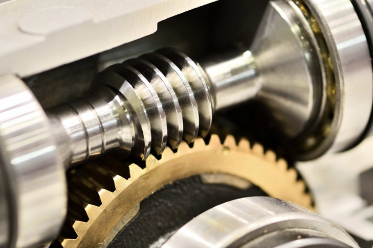
Image Credit: Dmitry Kalinovsky/Shutterstock.com
Rack and Pinion Gears
Rack and pinion gears are a pair of gears comprised of a gear rack and a cylindrical gear referred to as the pinion. The gear rack can be considered as a gear of infinite radius (i.e., a flat bar) and is constructed with straight teeth cut or inserted on the bar’s surface. Depending on the type of pinion gear with which it is mated, the gear rack’s teeth are either parallel (when mated with spur gears) or angled (when mated with helical gears). For either of these rack designs, rotational motion can be converted into linear motion or linear motion can be converted into rotational motion.
Some of the advantages of a rack and pinion gear pair are the simplicity of the design (and the low cost of manufacturing) and high load carrying capacities. Despite the advantages of this design, gears which employ this approach are also limited by it. For example, transmission cannot continue infinitely in one direction as motion is limited by the designated length of the gear rack. Additionally, rack and pinion gears tend to have a greater amount of backlash (i.e., additional space between mated gear teeth) and, consequently, the teeth experience a significant amount of friction and stress.
Some of the common applications of rack and pinion gear pairs include the steering system of automobiles, transfer systems, and weighing scales.
(Note: whereas in rack and pinion gears, the term “pinion” refers to the gear which meshes with the gear rack, in pairs of other types of gears, the term “pinion” refers, when applicable, to the gear with the smallest number of teeth)
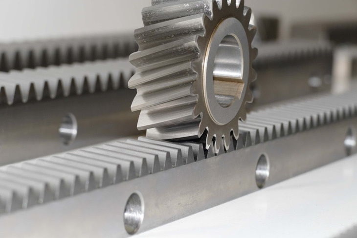
Image Credit: MMilda/Shutterstock.com
Table 1 – Characteristics of Gears by Type
|
Type of Gear |
Characteristics |
|
Spur |
|
|
Helical |
|
|
Bevel |
|
|
Worm |
|
|
Rack and Pinion |
|
Gear Selection Considerations
Gears are employed in a variety of mechanical devices, and, consequently, several different types and designs are available. The suitability of each type of gear and its exact design for a motion or power transmission application is dependent on the specifications and requirements of the application. Some of the principal factors which may be considered when designing and choosing a gear include:
- Operational and environmental conditions
- Dimensional restrictions
- Transmission requirements
- Design standards
- Costs
Operational and Environmental Conditions
The operational and environmental conditions of the gear application largely influence the optimal type and design of gear as the conditions can affect the gear’s performance and durability. Some of the operational conditions which may affect a gear are the amount of weight applied, noise and vibration produced, and friction and stress placed on the teeth, while some of the environmental conditions which may affect a gear include temperature, humidity, and sanitation and cleanliness. These conditions influence a variety of gear design factors, including the construction material, surface treatments, and lubricant type and lubrication method.
Gear Construction Material
Gears are available in a variety of construction materials—e.g., cast iron and steel, fiber, nylon, and stainless steel—with each of these materials offering particular manufacturing and operational advantages. For example:
- Cast iron is used for its ease of manufacturing and low cost, which make it suitable for high-volume or large-scale production applications which do not require high precision specifications.
- Steel, such as carbon and alloy steel, is used for its high hardness and tensile strength, which make it suitable for producing highly durable gears.
- Nylon is a low-cost material with lightweight and non-corrosive properties, which make it suitable for large-scale production and light-load applications.
Gear Surface Treatments
Some of the surface treatments available for gears include grinding and heat treatment.
Grinding down the surface of the gear teeth can decrease the amount of noise produced during operation, increase the amount of force which can be transmitted, and affect the gear’s precision classification. However, grinding also increases the overall cost of production.
There are several heat treatment services available for gears include surface hardening, tempering, normalizing, annealing, and carburizing. These processes can affect the properties of the gear material, such as increasing its hardness and strength, which can improve the gear’s overall durability and longevity.
Gear Lubrication
If adequately and properly applied, gear lubricants can help to extend the overall lifespan of a gear by preventing or reducing the amount of stress and fatigue experienced by the gear body and teeth. However, both the optimal type of lubricant and lubrication method are dependent on the requirements and specifications of the application.
When selecting a lubricant, consideration should be given to the potential lubricant’s viscosity, load pressure capacity, thermal and chemical stability, and water separating, anti-foaming, and corrosion resisting properties within the operational and environmental conditions of the application. Given the employment of the proper lubricant, some of the benefits include the reduction of friction between gear teeth, mitigation of heat generated, and lowering of the amount of noise and vibration produced during operation.
Once a suitable lubricant is selected, it must be properly applied. Proper application of a lubricant depends on a variety of factors, including operation speed and load. The most common application methods for gear lubrication include grease lubrication, splash lubrication, and forced oil circulation lubrication.
- In grease lubrication, grease (rather than oil) is applied directly to the gears and components. The viscosity of the grease allows it to provide lubrication for longer periods before breaking down or wearing off, allowing for less frequent reapplication. This lubrication method is most suitable for open or enclosed gear systems operating at low speeds and with light loads.
- In splash lubrication, the rotation of the gears distributes the lubricant across the gear device components. This lubrication method is suitable for enclosed gear systems which operate at higher speeds and with greater loads than grease lubrication. However, precise oil levels and temperatures must be maintained.
- In forced circulation lubrication, the lubricant is applied to the gear teeth via an oil pump, which delivers the lubricant to the proper component by dropping (via piping), spraying, or misting it into place. While this method is highly effective, especially for high-speed or heavy-duty applications, it is also more expensive than other methods due to the number of components required for a complete system.
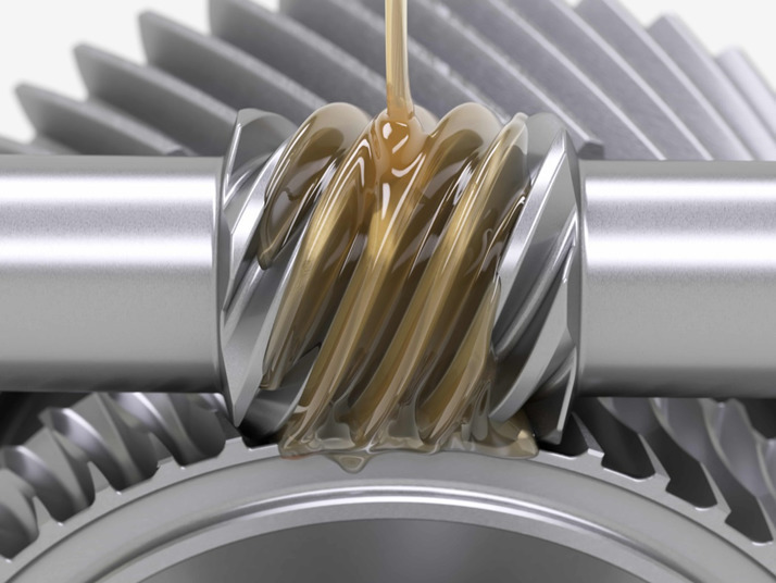
Image Credit: maxuser/Shutterstock.com
Dimensional Restrictions
Beyond the operational and environmental conditions of the application, gears and their designs are also limited by the dimensional specifications—i.e., physical space—of the mechanical device.
For example, gears are typically mated to suit the center distances between machine shafts. However, some applications may require an adjustment of the center distances to better fit within the dimensions of the mechanical gear system or machine, which necessitates a profile shift—i.e., deviation from the standard tooth profile. Deviation from the standard tooth profile typically means adjusting—either increasing or decreasing—the tooth’s thickness. This adjustment changes the center distance, as well as the strength of the gear’s teeth.
Other methods of managing dimensional restrictions include employing gear types and designs that are better suited for limited- or restricted-space applications. For example, internal-external gear pairs allow for the gears and their shaft or base components to be positioned closer together than external-only gear pairs, and hypoid gears allow for components to be placed lower within the machine or system, allowing for more space above.
Transmission Requirements
Gears are used to transfer motion and torque between machine components in mechanical devices. Depending on the design and construction of the gear pair employed, gears can change the direction of movement and/or increase the output speed or torque. The specification and requirements of the applications—i.e., whether they need to change direction, increase speed or torque, or both—influence the required and optimal gear type, design, and configuration.
Change in Direction
In regard to gears, change of direction can refer either to a change in the direction of rotation or a change in the axis of motion. For example, parallel axes configurations which employ external-only gear pairs allow for a change in the output rotation, but not a change in the axis of rotation. On the other hand, intersecting and non-parallel, non-intersecting axes configurations allow for a change in both the output rotation and the axis of motion. The directional change requirements also influence the optimal type of gear as each type is characterized by a particular configuration (e.g., spur gears employ the parallel configuration, bevel gears the intersecting configuration, and screw gears the non-parallel, non-intersecting configuration.
Change in Speed or Torque
When mated gears are of different sizes, the resultant output torque and rotational speed are affected as the gear ratio is not equal to (i.e., greater or less than) one. The term “gear ratio” refers to the ratio of the output to the input, and is illustrated by the following equation where output is typically expressed as the number of teeth on the driven gear and input is typically expressed as the number of teeth on the driving gear:
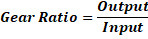
Depending on which of the driving and driven gear is the larger and which is the smaller, and consequently which has more teeth and which has less, the resultant gear ratio can produce output speed and torque which are increased or reduced with respect to the input speed and torque. Additionally, as there is an inverse relationship between the two values, either speed can be increased, or torque can be increased, but not both.
For torque, the gear ratio represents the ratio of the output torque to the input torque. Therefore, the output torque can be calculated using the following equation where t represents torque:
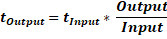
Based on the above equation, if the pinion gear is attached to the driven shaft (i.e., output), then the output torque decreases. On the other hand, if the pinion gear is attached to the driving shaft (i.e., the input), then the output torque increases.
Because torque and speed have an inverse relationship, output speed can be calculated using the following equation where input speed is multiplied by the reciprocal of the gear ratio used in the above torque equation:
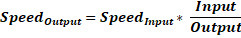
If the pinion gear is attached to the driven shaft (i.e., output), then the output speed increases. This result is referred to as gearing up. On the other hand, if the pinion gear is attached to the driving shaft (i.e., the input), then the output speed decreases. This result is referred to as gearing down.
Design Standards
There are a wide variety of specifications for gears. But unfortunately, no universal industrial standards exist which define how a gear should be designed and manufactured. Typically, gears are produced either to the standards set by the individual manufacturer or to suit the design and specifications of a particular machine or system rather than those machines and systems being designed around a standard gear component. The former case makes it more difficult to find the proper gear type and design for an application among the standard components available from gear manufacturers, while the latter case increases the difficulty and cost of finding replacements for the customized part.
While there are no universal gear standards, some countries have implemented their own industrial gear standards, especially in regards to precision gears. For example, in the United States, gears can be classified by standards set by the American Gear Manufacturers Association (AGMA), while Japan classifies gears by Japan Industrial Standards (JIS) and Germany by the German Institute for Standardization (DIN) standards.
Costs
When producing a custom gear, the cost of manufacturing is influenced by several factors, including the gear design, construction material, surface treatments and finishes, precision standards, and lubricant and lubrication method. Industry professional and procurements agents also need to consider the durability and longevity of the custom gear to calculate the optimal maintenance and replacement schedule. While it is necessary to choose a gear which effectively fulfills the requirements of the application, it is also important to keep in mind the overall lifecycle costs—i.e., the production, gear repair and maintenance, and replacement costs—of the chosen gear to better determine whether the device is worth the investment. For some applications, a standard, off-the-shelf gear may fulfill the requirements at a much lower cost.
Application of Different Types of Gears
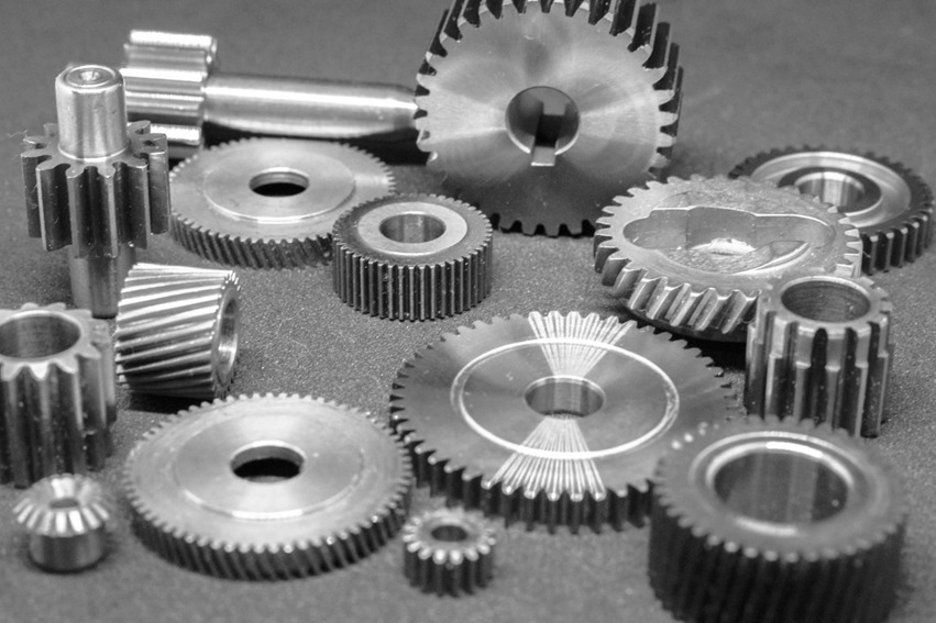
Image Credit: mrqi/Shutterstock.com
Gears are devices used throughout industry for a variety of mechanical machines and systems. Several types of gears are available and employed in a wide range of residential, commercial, and industrial applications, including:
- Aircrafts
- Automobiles
- Clocks
- Marine systems
- Material handling equipment
- Measuring instrumentation
- Power plants
- Pumps
One of the most widespread manner in which gears are applied is in gearboxes, which are devices comprised of gears contained within an enclosure or housing. These devices utilize a wide range of gear types— including worm gears, bevel gears, helical gears, and spur gears—and are engineered to perform a specific motion or power transmission task within the machine system, from changing the speed and torque to changing output shaft direction. Similar to most gear systems, gearboxes have a variety of uses, such as in automobiles and other motorized vehicles.
Table 2, below, indicates some of the common industries and applications of the types of gears previously mentioned.
Table 2 – Industries and Applications of Gears by Type
|
Type of Gear |
Common Industries and Applications |
|
Spur |
|
|
Helical |
|
|
Bevel |
|
|
Worm |
|
|
Rack and Pinion |
|
Key Terms
Driving Gear: The gear closest to the power source (motor or engine) and attached to the driving shaft that provides the initial rotational input
Driven Gear: The gear or toothed component attached to the driven shaft which is impacted by the driving gear and exhibits the final output
Idler Gear: A gear placed between the driving gear and driven gear; typically employed to allow for the transmission of motion without a change in the direction of rotation
Gear Ratio: The ratio between the output value to the input value; typically expressed as the number of teeth of the driven gear (output) to number of teeth of the driving gear (input)
Tooth Profile: The cross-sectional shape of the gear’s teeth
Axes Configuration: The orientation of the axes—along which the gear shafts lay and around which the gears rotate—in relation to each other
Torque: Also referred to as moment or moment of force; the measure of the rotational or twisting force which causes an object to rotate
Axial Load: The thrust force parallel to the gear shaft
Efficiency: The percentage value of the ratio of output power (i.e., input power minus power loss) to the input power
Summary
This guide provides a basic understanding of gears, the types available, their applications, and considerations for use.
For more information on related products, consult Thomas guides and white papers or visit the Thomas Supplier Discovery Platform, where you will find information on over 500,000 commercial and industrial suppliers.
Sources
- https://www.britannica.com/technology/gear
- http://www.cs.cmu.edu/~./rapidproto/mechanisms/chpt7.html
- http://www.cs.cmu.edu/~./rapidproto/mechanisms/chpt2.html
- http://mae3.eng.ucsd.edu/machine-design/gear-ratios
- https://www.explainthatstuff.com/gears.html
- https://www.creativemechanisms.com/gear
- https://www.engineersedge.com
- https://www.machinedesign.com/motorsdrives/noncircular-gears-make-unconventional-moves
- http://www.sci.brooklyn.cuny.edu
- http://www2.mae.ufl.edu/designlab/Class%20Projects/Background%20Information/Gears%20and%20gearing.htm
- https://www.amtechinternational.com/internal-external-spur-gear/
- https://me-mechanicalengineering.com/comparison-between-involute-and-cycloidal-tooth-profiles/
- http://web.mit.edu/harishm/www/papers/involuteEWC.pdf
- http://mathworld.wolfram.com/Trochoid.html
- https://fzemanufacturing.com/blog/shaft-manufacturing-process/
Other Gears Articles
- Types of Sprockets – A Thomas Buying Guide
- All About Spur Gears – What they Are and How They Work
- About Clutches – A Brief Guide
- All About Bevel Gears – What they Are and How They Work
- All About Helical Gears – What They Are and How They Work
- All About Worm Gears – What They Are and How They Work
- All About Rack and Pinion Gears – What They Are and How They Work
- Gear Materials, Classification and Application
- Definitions of Gear Terminology
- Top Gears Manufacturers and Suppliers