Introduction
As you know that before the internet and television came, radio broadcasting was the major information and news medium. Thus, Radio broadcasting has done by FM or AM modulation. In FM modulation the frequency got modulated while in AM amplitude changes. Though, AM broadcasting is older than the FM. At first, AM got invented in 1920. Later, it has not used like FM signals, but still, for emergency broadcasting sometimes it is considered the best way.
So, if someone is an electronic or a telecommunication engineer, it’s better to learn about it. And, since it’s not difficult to make and can be easily created, therefore, in this article we will try to make and understand the Simple AM Radio Receiver Circuit At Home.
Hardware Components
The following components are required to make AM Radio Receiver Circuit
| S.no | Component | Value | Qty |
|---|---|---|---|
| 1. | Electrolytic Capacitor | 10uf | 2 |
| 2. | Resistor | 1M, 22k, 4.7K, 1K, | 1, 1, 1, 1 |
| 3. | Ceramic Capacitor | 0.1uf, 470pF | 1, 1 |
| 4. | Transistor | BC547, 2n2222 | 1, 1 |
| 5. | Inductor | 200uH | 1 |
| 6. | Variable Resistor | 4.7K to 10K | 1 |
| 7. | Trim Capacitor | 4-40pf | 1 |
| 8. | Speaker | 8 Ohm | 1 |
| 9. | Battery | 9v | 1 |
| 10. | Antenna | – | 1 |
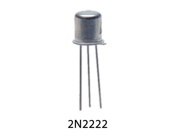
2n2222 Pinout
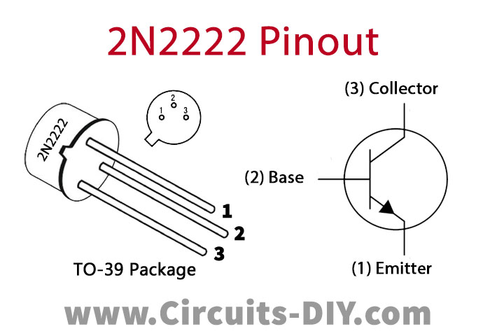
For a detailed description of pinout, dimension features, and specifications download the datasheet of 2n2222
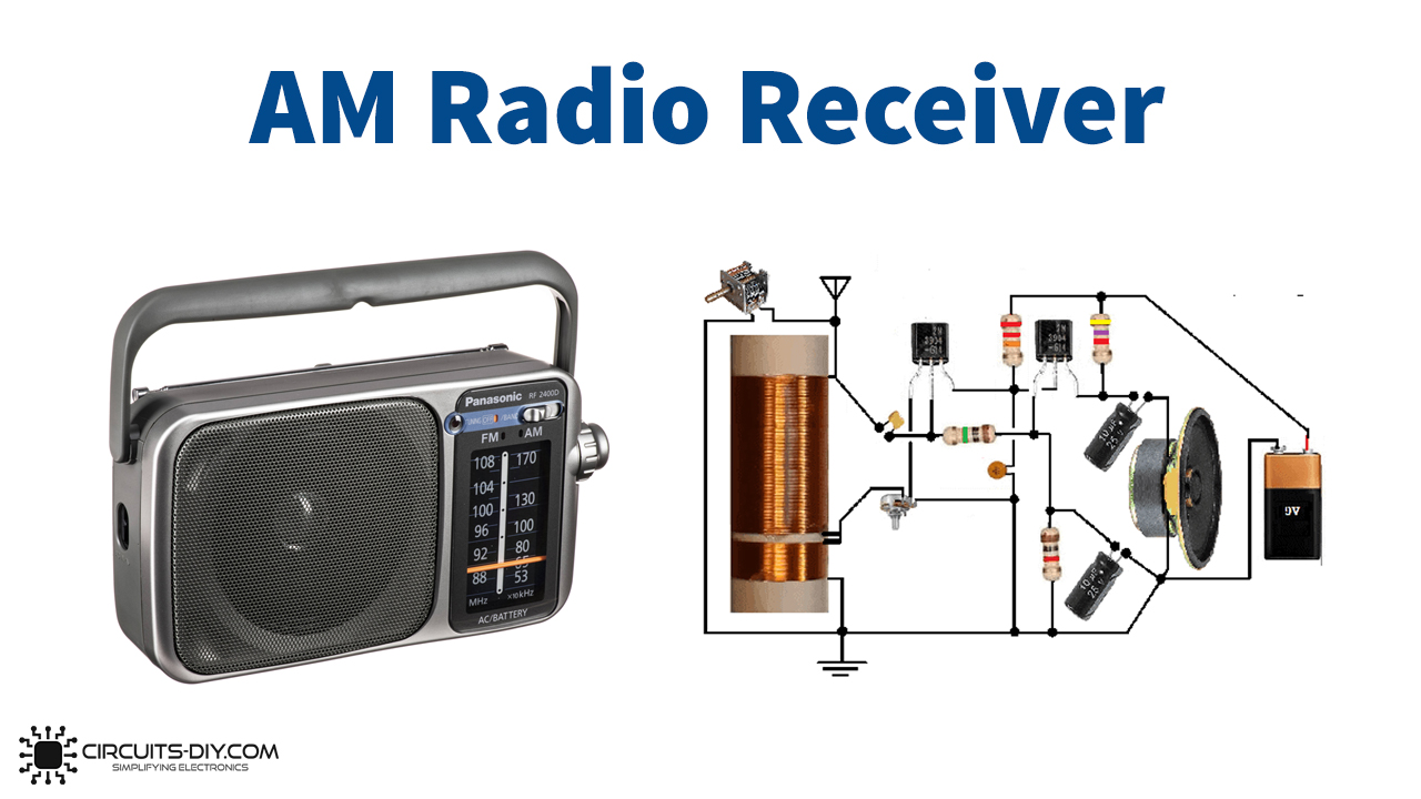
AM Radio Receiver Circuit
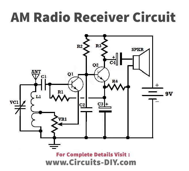
Working Explanation
In this Simple AM Radio Receiver, the variable capacitor and coil together are making the tuned circuit or the tank circuit. This circuit takes the signal from the antenna, adjusts the desired frequency, and gives it to the transistor Q1. The transistor there amplifies the given modulated signal and demodulates the signal. Now transistor Q2 is for the output audio. At the emitter of the NPN transistor ( first transistor Q1), a part of the signal is fed back to the coil L1. The value of this feedback can be adjusted by the potentiometer wired in the circuit. Capacitor C4 is connected at the collector of Q2, which is the output of a circuit, hence driving the load. The capacitor C3 is charged by transistor Q2 and feeds transistor Q1 with the help of Resistor R1.
Application and Uses
- For radio broadcasting.
- To understand amplitude modulation practically.