

What is an Electrical Resistor?
A resistor (also known as an electrical resistor) is defined as a two-terminal passive electrical element that provides electrical resistance to current flow. Resistance is a measure of the opposition to the flow of current in a resistor. The larger a resistor’s resistance, the greater the barrier against the flow of current. There are many different types of resistors, such as a thermistor.
In an electrical and electronic circuit, the primary function of a resistor is to “resist” the flow of electrons, i.e., electric current. That is why it is called a “resistor”.
Resistors are passive electrical elements. This means they cannot deliver any energy to the circuit, and instead, they receive energy and dissipates it in the form of heat as long as a current flowing through it.
Different resistors are used in an electrical and electronic circuit to limit the current flow or produce voltage drops. Resistors are available in many different resistance values from fractions of Ohm (Ω) to millions of Ohms.
According to ohm’s law, the voltage (V) across a resistor is directly proportional to the current (I) flowing through it. Where the resistance R is the constant of proportionality.
What Does a Resistor do?
In an electrical and electronic circuit, resistors are used to limit and regulate current flow, divide voltages, adjust signal levels, bias active elements, etc.
For example, many resistors are connected in series used to limit the current flowing through the light-emitting diode (LED). Other examples are discussed below.
Protect Against Voltage Spikes
A snubber circuit is where a series combination of a resistor and a capacitor are connected in parallel with the thyristor used to suppress the rapid rise in voltage across a thyristor. This is known as a snubber circuit used to protect the thyristor against High  .
.
Resistors are also used to protect LED lights against voltage spikes. LED lights are sensitive to high electrical current, and hence they will get damaged if a resistor is not used to control the flow of electrical current through the LED.
Provide Proper Voltage By Creating Voltage Drop
Each element in an electrical circuit, like a light or a switch, requires a specific voltage. For that, resistors are used to provide proper voltage by creating a voltage drop across elements.
What is Electrical Resistance Measured in (Resistor Units)?
The SI unit for a resistor (the electrical resistance is measured in) Ohm and is represented as Ω. The unit ohm (Ω) is named honor of the great German physicist and mathematician Georg Simon Ohm.
In SI system, an ohm is equal to a 1 volt per ampere. Thus,

Therefore, the resistor is also measured in volt per ampere.
Resistors are manufactured and specified over a wide range of values. Hence, the derived units of resistors are made according to their values such as milliohm (1 mΩ = 10-3 Ω), kiloohm (1 kΩ = 103 Ω) and megaohm (1 MΩ = 106 Ω), etc.
Electrical Resistor Circuit Symbol
There are two main circuit symbols used for electrical resistors. The most common symbol for a resistor is a zig-zag line which is widely used in North America.
The other circuit symbol for a resistor is a small rectangle widely used in Europe and Asia, and this is termed the international resistor symbol.
The circuit symbol for resistors as shown in the image below.

Series and Parallel Resistors
Resistors in Series Formula
The circuit below shows a number of resistors n connected in series.

If two or more resistors are connected in series, then the equivalent resistance of the series-connected resistors is equal to the sum of their individual resistances.
Mathematically, this is expressed as


In a series connection, the current flowing through each individual resistor remains constant (i.e. the current through each resistor is the same).
Example
As shown in the circuit below, three resistors, 5 Ω, 10 Ω, and 15 Ω, are connected in series. Find the equivalent resistance of the series-connected resistors.

Solution:
Given Data:  and
and 
According to formula,


Thus, we get the equivalent resistance of series connected resistors is 30 Ω.
(note that the circuit diagram above says 25 Ω. This is a typo, the correct answer is 30 Ω)
Resistors in Parallel Formula
The circuit below shows a number of resistors n connected in parallel.
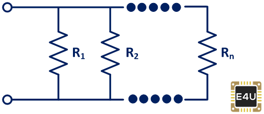
If two or more resistors are connected in parallel, then the equivalent resistance of the parallel-connected resistors is equal to the reciprocal of the sum of the reciprocals of the individual resistances.
Mathematically, this is expressed as


In a parallel connection, the voltage flowing through each individual resistor remains constant (i.e. the voltage through each resistor is the same).
Example
As shown in the circuit below, three resistors with resistance 10 Ω, 20 Ω, and 30 Ω, are connected in parallel. Find the equivalent resistance of the parallel-connected resistors.

Solution:
Given Data:  and
and 
According to the formula for parallel resistance,


Thus, we get an equivalent resistance of the parallel connected resistors equal to 5.455 Ω.
Resistor Circuits (Example Applications)
LED Current Limiting Resistor
Limiting current is very important in an LED. If too much current is flowing through an LED, it will get damaged. Therefore, a current limiting resistor is used to limit or reduce the current into an LED.
Current limiting resistors are connected in series with an LED to limit the current flowing through the LED to a safe value. For example, as shown in the image below, the current limiting resistor is connected in series with the LED.

Calculate the Necessary Value of Current Limiting Resistor
While calculating the value of a current-limiting resistor, we need to know three specifications or characteristics value of the LED:
- LED forward voltage (from datasheet)
- LED maximum forward current (from datasheet)
- VS = supply voltage
The forward voltage is the voltage required to make an LED on, and it is usually between 1.7 V to 3.4 V, depending on the color of the LED lights. The maximum forward current is the continuous current flowing through the LED, and it is usually around 20 mA for basic LEDs.
Now, we can calculate the necessary value of the current limiting resistor using the following equation,

Where,  = Supply Voltage
 = Forward Voltage
 = maximum forward current
Let’s see an example of calculating the necessary value of the current limiting resistor using the above formula.
Example
As shown in the image below, a battery voltage of 3.8 V has used to power an LED. The forward voltage and maximum forward current of an LED are 3.1 V, and 30 mA. find the necessary value of the current limiting resistor.

Solution:
Given Data:  ,
,  ,
, 
Put this value into equation,

So, we get the necessary value of the resistor to limit the current flowing through an LED is 23.3 Ω.
Pull-up Resistors
Pull-up Resistors are resistors used in electronic logic circuits to ensure a known state for a signal.
In other words, Pull-up resistors are used to ensure that a wire is pulled to a high logical level when there is no input condition. A pull-down resistor works similar to the pull-up resistors, except that they pulled a wire to a logical low level.
Modern IC’s, microcontrollers, and digital logic gates have many inputs and output pins, and these inputs and outputs need to be correctly set. Hence, pull-up resistors are used to ensure correctly bias the input pin of microcontrollers or digital logic gate’s input to a known state.
Pull-up resistors are used in combination with transistors, switches, buttons, etc., which interrupt the physical connection of subsequent components to the ground or VCC. For example, the pull-up resistor circuit is shown in the image below.

As shown, when the switch is closed, the input voltage (Vin) at the microcontroller or gate goes to the ground, and when the switch is open, the input voltage (Vin) at the microcontroller or gate is pulled up to the level of input voltage (Vin).
Hence, the pull-up resistor can bias the microcontroller’s input pin or gate when the switch is open. Without a pull-up resistor, the inputs at the microcontroller or gate would be floating, i.e., in a high impedance state.
A typical value of pull-up resistor is 4.7 kΩ but it can vary depending on the application.
Voltage Drop Across a Resistor
The voltage drop across a resistor is nothing but simply a value of voltage across the resistor. The voltage drop is also known as IR drop.
As we know, a resistor is a passive electrical element that provides electrical resistance to the flow of current. Thus, according to ohm’s law, it will create a voltage drop when the current passes through a resistor.

Mathematically, voltage drop across a resistor can be expressed as,

Sign for IR Drops (Voltage Drops)
To determine the sign for the voltage drops across a resistor, a direction of current is very important.
Consider a resistor of resistance R in which current (I) flows from point A to point B, as shown in the image below.
Therefore, point A is at a higher potential to point B. If we travel from A to B, V = I R negative, i.e., -I R (that is, fall in potential). Similarly, if we travel from point B to point A, V = I R positive, i.e., +I R (that is, rise in potential).
Hence, it is clear that the sign of voltage drop across a resistor depends on the direction of current through that resistor.
Resistor Color Codes
Resistor Colour Codes are used to identify resistive or resistance value and percentage tolerance of any resistors. The resistor’s color codes use colored bands to identify it.
As shown in the figure below, there are four color bands printed on the resistor. Out of the three bands are printed side by side, and the fourth band is printed slightly away from the third band.

The first two bands from the left side indicate significant figures, the third band indicates the decimal multiplier, and the fourth band indicates the tolerance.

The table below shows significant figures, decimal multiplier, and tolerance for different color coding of resistors.

Key Points:
- The Gold and Silver band is always placed to the right.
- The resistor value is always read from left to right.
- If there is no tolerance band, find the side with a band near to a lead and make that the first band.
Example (How to Calculate Resistor Value?)
As shown in the image below, a carbon color-coded resistor has the first ring of green, second of blue, third of red, and fourth of golden color. Find the specifications of the resistor.

Solution:
As per table of color coding of resistors,
| Green | Blue | Red | Golden |
| 5 | 6 | 102 |  |

Thus, the value of resistance is  with tolerance.
Hence, the value of resistance is in between


Hence, the value of resistance is in between  and
and  .
.
Character or Letter Coding (RKM Code)
Sometimes, resistors can be so small that color coding is difficult to apply. In such cases, a character or letter coding is used for specifications of resistors. It is also referred to as RKM code.
The characters used for coding resistors are R, K, and M. When there is a character between two decimal numbers, it acts as a decimal point. For example, the character R indicates Ohms, K indicates Kilo ohms, and M indicates Mega ohms. Let’s see examples of this.
| Resistance | Letter Code |
| 0.3 Ω | R3 |
| 0.47 Ω | R47 |
| 1 Ω | 1R0 |
| 1 KΩ | 1K |
| 4.7 KΩ | 4K7 |
| 22.3 MΩ | 22M3 |
| 9.7 MΩ | 9M7 |
| 2 MΩ | 2M |
Tolerance is indicated as
| Character | Tolerance |
| F |  |
| G |  |
| J | |
| K |  |
| M |  |
Example – Resister with letter code:
| Resistance | Letter Code |
 | 3R5J |
 | 4R7K |
 | 9M7G |
Types of Resistors
There are various types of resistors, each with its own unique properties and specific use cases.
There are two basic types of resistors available Fixed resistors and Variable resistors. Both the types are listed below.
Fixed Resistors
Fixed resistors are the most widely used type of resistor. They are widely used in electronics circuits to adjust and regulate proper conditions in a circuit. The types of fixed resistors are listed below.
- Carbon Composition Resistors (Carbon Resistors)
- Carbon Pile Resistors
- Carbon Film Resistors
- Thermistor (Thermal Resistor)
- Wire Wound Resistors
- Surface Mount Resistors
- Metal Film Resistors
- Metal Oxide Film Resistors
- Thick Film Resistors
- Thin Film Resistors
- Foil Resistors
- Printed Carbon Resistors
- Ammeter Shunts Resistor (Current-Sensing Resistor)
- Grid Resistor
Variable Resistors
Variable resistors consist of one or more fixed resistor elements and a slider. These give three connections to the element; two are connected to the fixed resistor element, and the third is the slider. By moving the slider to different terminals, we can vary the value of resistance.
The types of variable resistors are listed below.
- Adjustable Resistors
- Potentiometers
- Variable Resistors (Rheostat)
- Resistance Decade Box (Resistor Substitution Box)
- Varistors (Non-Linear Resistor)
- Light Dependent Resistor (LDR) or Photoresistor
- Trimmers
Other special variety of resistors include:
- Water Resistor (Water Rheostat, Liquid Rheostat)
- Ballast Resistor
- Phenolic Molded Compound Resistor
- Cermet Resistors
- Tantalum Resistors
Resistors Sizes (Most Common Resistor Values)
Resistors sizes are organized into a set of different series of standard resistor values. In 1952 the International Electrotechnical Commission decided to determine the standard resistance and tolerance values to increase compatibility between components and ease manufacturing of resistors.
These standard values are referred to as the E series of the IEC 60063 preferred number values. These E series are classified as E12, E24, E48, E96, and E192 with 12, 24, 48, 96, and 192 with different values within each decade.
The most common resistor values are listed below. It is E3, E6, E12, and E24 standard resistor values.
- E3 standard resistor series:
The E3 resistor series are most common resistor values used in electronics industry.
| 1.0 | 2.2 | 4.7 |
- E6 standard resistor series:
The E3 resistor series is also most commonly used, and it provides a wide range of common resistors values.
| 1.0 | 1.5 | 2.2 |
| 3.3 | 4.7 | 6.8 |
- E12 standard resistor series:
| 1.0 | 1.2 | 1.5 |
| 1.8 | 2.2 | 2.7 |
| 3.3 | 3.9 | 4.7 |
| 5.6 | 6.8 | 8.2 |
- E24 standard resistor series:
| 1.0 | 1.1 | 1.2 |
| 1.3 | 1.5 | 1.6 |
| 1.8 | 2.0 | 2.2 |
| 2.4 | 2.7 | 3.0 |
| 3.3 | 3.6 | 3.9 |
| 4.3 | 4.7 | 5.1 |
| 5.6 | 6.2 | 6.8 |
| 7.5 | 8.2 | 9.1 |
Resistor tolerance are generally specified , ,,, and .
What is a Resistor Made of?
Depending on the application, there are variety of materials used to make resistor.
- Resistors are made from carbon or copper, making it difficult for the electric current to flow through a circuit.
- The most common type and general-purpose resistor is a carbon resistor best suited in low power electronic circuits.
- Manganin and constantan alloys are used for manufacturing standard wire-wound resistors as they have high resistivity and low-temperature coefficient of resistance.
- Manganin foil and wire are used to manufacture resistors such as ammeter shunts, as manganin has almost zero temperature coefficient resistance.
- Nickle-Copper-Manganese alloy is used to manufacture standards resistors; wire wound resistors, precision wire wound resistors, etc. This alloy having a composition: Nickel = 4%; Copper = 84%; Manganese = 12%.
What Are the Common Use of Resistor (Applications of Resistor)
Some of the applications of the resistor include:
- Resistors are used in amplifiers, oscillators, digital multi-meter, modulators, demodulators, transmitters, etc.
- Photoresistors are used in burglar alarms, flame detectors, photographic devices, etc.
- Wire wound resistors are used in shunt with ampere meter where high sensitivity, balanced current control, and accurate measurement are required.
